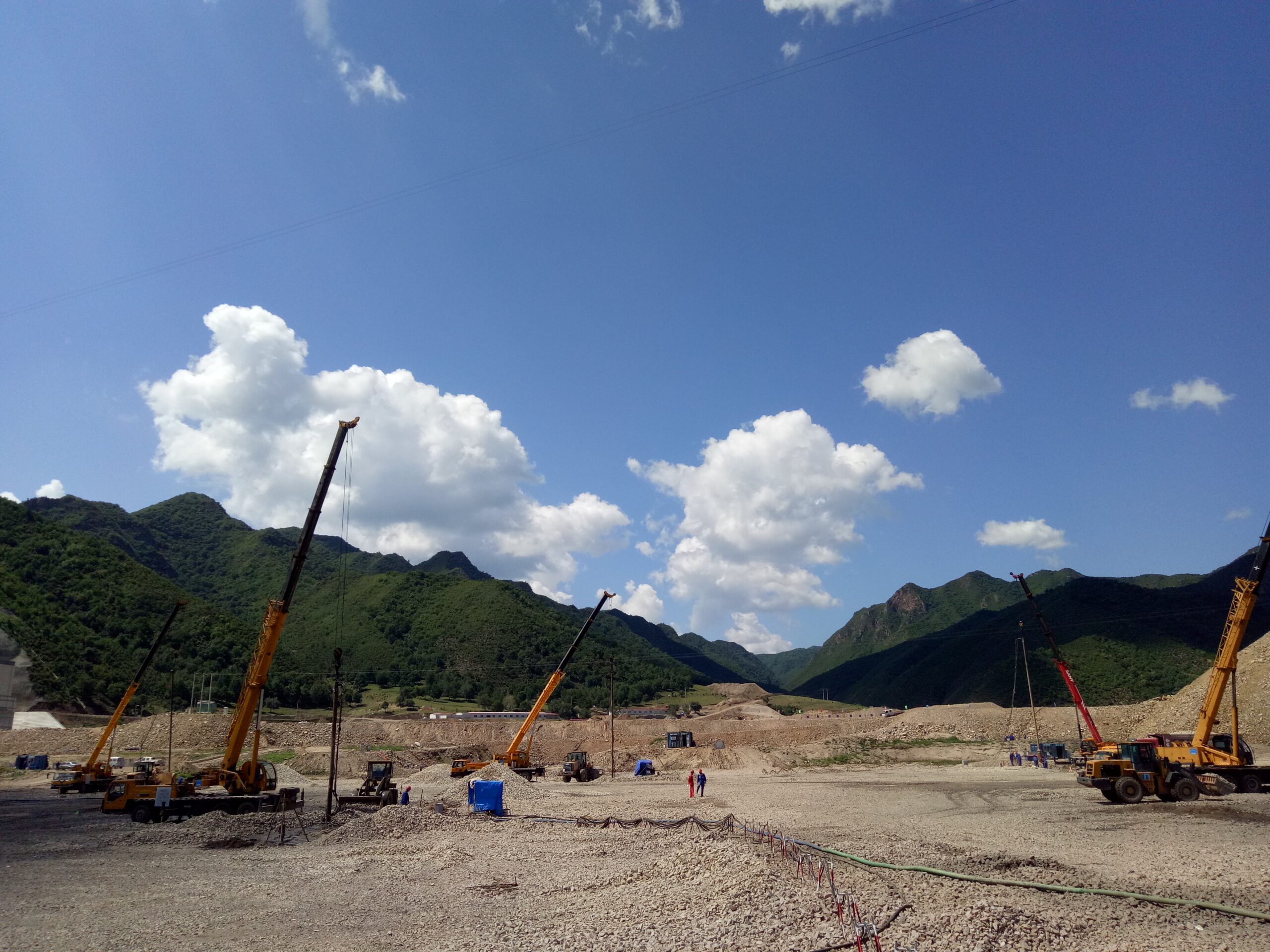
Vibroflotation Construction Project for Section S2 of the Karnaphuli River Underwater Tunnel, Chattogram, Bangladesh
Project Background and Strategic Significance
The Bangabandhu Sheikh Mujibur Rahman Tunnel (popularly known as the Karnaphuli River Underwater Tunnel) in Chattogram, Bangladesh, represents a monumental infrastructure breakthrough in South Asia. As a critical segment of the Belt and Road Initiative and a vital link in the Bangladesh-China-India-Myanmar (BCIM) Economic Corridor, the tunnel physically connects Chattogram city on the north bank to the developing industrial zone on the south bank of the Karnaphuli River.
Section S2 encompasses the critical east bank shield tunnel approach, open-cut transition zones, and embankment portals. Constructing a heavy-duty underwater transportation tunnel through dynamic estuarine geology presents formidable geotechnical challenges. The primary structural threat to the approach sections and portal cuts was soil liquefaction under seismic excitation and cyclic load transference. To ensure long-term structural integrity, strict differential settlement tolerances, and operational safety, a comprehensive soil improvement campaign was mandated. Vibro replacement (stone column construction) was selected as the core ground modification methodology to remediate the vulnerable subsoils and construct a reinforced composite foundation.
Geological Profile & Engineering Challenges
Subsurface Stratigraphy
The project area lies within the active alluvial-deltaic plain of the Karnaphuli River, characterized by complex, variable, and young sedimentary deposits. Geotechnical site investigations revealed a multi-layered soil profile:
Holocene Alluvial Deposits (Q4 Upper Stratum): Composed of loose to medium-dense saturated silty sands, fine sand, and soft interbedded cohesive deposits extending to depths of 15 to 22 meters below the natural ground line. The water table across the site is exceptionally high, fluctuating near the ground surface due to daily tidal influences from the nearby Bay of Bengal.
Pleistocene Alluvial Deposits (Q3 Lower Stratum): Stiff to very stiff silty clays, clayey silts, and dense sand strata underlying the Q4 formation. These layers exhibit low compressibility, moderate to high shear strength, and localized semi-lithified cohesive horizons.
Geotechnical Hazards & Liquefaction Potential
The primary geotechnical hazard facing Section S2 was the severe liquefaction susceptibility of the Q4 saturated sand strata. Under cyclic seismic shaking, excess pore water pressure (u) builds up rapidly within uncompacted granular soils. When excess pore pressure equals the initial vertical effective stress , the effective stress drops to zero, causing the sandy soil to lose its shear strength entirely and behave like a liquid.
In the context of the Karnaphuli River Tunnel, localized or widespread liquefaction would trigger severe engineering consequences:
Loss of Bearing Capacity: Severe reduction in lateral and vertical subgrade reaction for the tunnel structures and retaining walls.
Excessive & Differential Settlement: Uncontrolled vertical displacement during and post-seismic events, leading to segmental lining distortion, joint leakage, or complete structural cracking.
Flotation and Hydrodynamic Instability: Buoyancy effects acting on buried hollow tunnel segments under high pore pressure regimes.
To eliminate these risks, ground modification was required to increase soil density, elevate horizontal stress states, and provide rapid pore pressure dissipation paths.
Technical Solution: Vibro Replacement (Stone Columns)
Mechanism of Ground Improvement
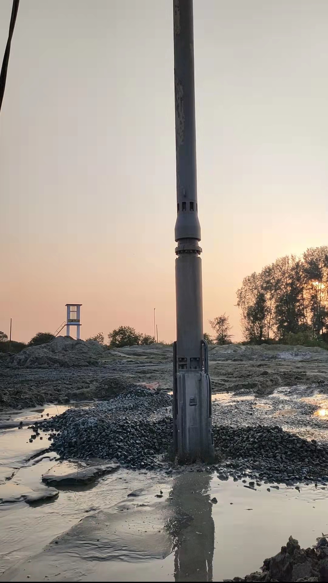
Vibro Replacement (Stone Column technique) improves non-cohesive and weak cohesive soils through three concurrent mechanisms:
In-situ Densification: Vibratory energy transmitted laterally by the probe forces loose sand particles into a tighter packing arrangement, significantly increasing relative density (Dr), friction angle, and Standard Penetration Test (N60) values.
Inclusion Reinforcement: Replacing soft soil columns with high-stiffness, dense aggregate columns creates a composite ground matrix. The stiffer stone columns attract higher stress concentrations, reducing overall stress on the surrounding matrix and limiting total settlement.
Pore Water Dissipation (Vertical Drainage): High-permeability stone columns act as vertical gravel drains, drastically shortening drainage path lengths and preventing the buildup of damaging excess pore water pressures during seismic events.
Design Specifications & Grid Geometry
The vibro replacement works were designed according to strict geotechnical performance criteria:
Target Diameter (d): 1.0 meter nominal diameter.
Pattern & Spacing (s): Triangular grid layout with 2.0-meter center-to-center spacing to maximize overlapping densification zones.
Average Column Length: Approximately 20.6 meters per column, ensuring penetration through the full thickness of liquefiable Q4 sands and anchoring into the stable Pleistocene (Q3) stratum.
Total Quantities: 13,480 linear meters of stone column installation across the designated S2 section.
Backfill Material: Hard, durable crushed basalt/granite rock, free from organic contaminants, graded between 20 mm and 75 mm, with a silt content of under 5%.
Execution Methodology & Equipment Deployment
Construction Methodology: Vibroflotation- 130kW Electric Top Feed Vibroflot
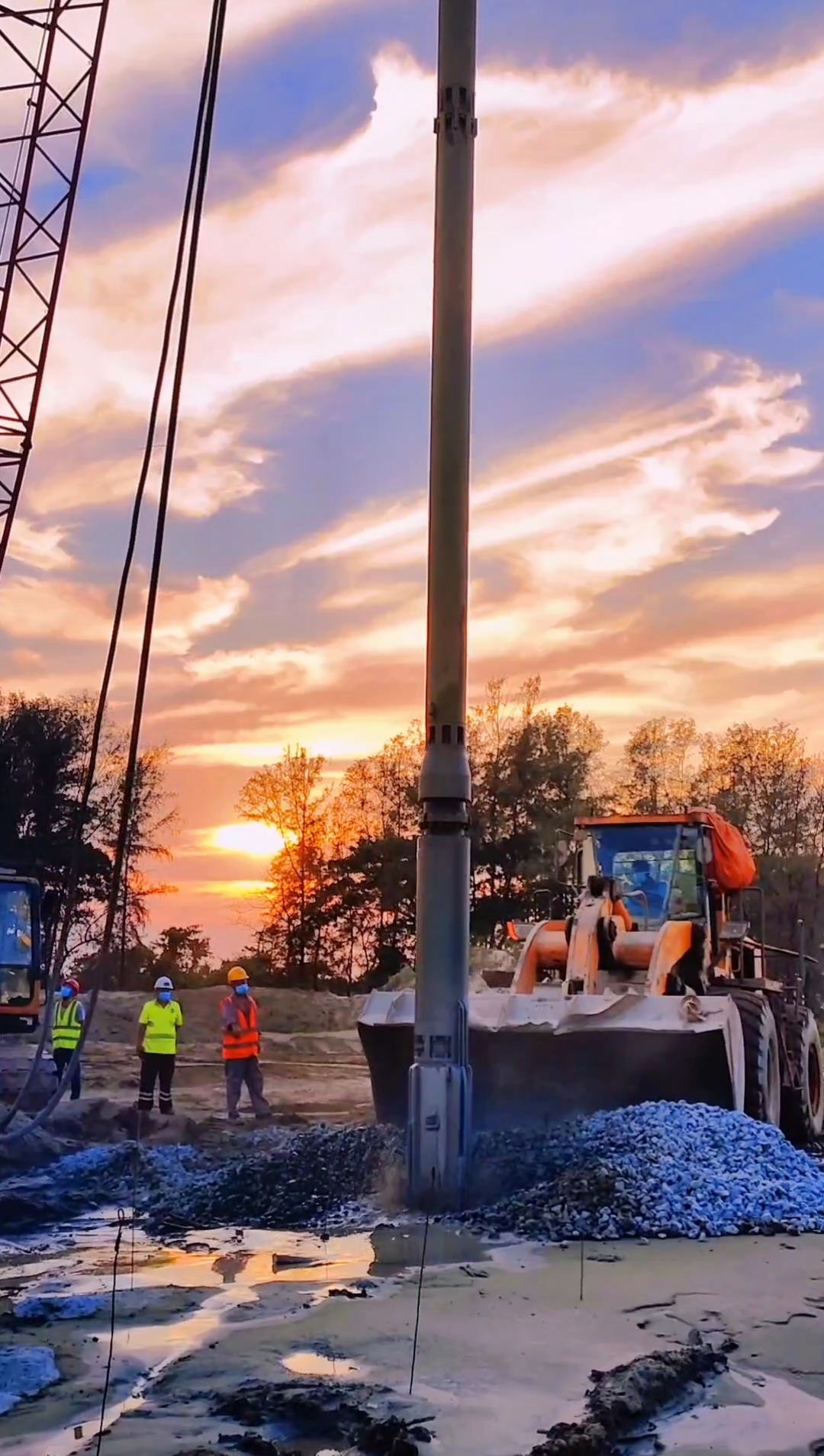
Given the high water table, loose saturated sands, and potential for borehole collapse, the Wet Top-Feed Vibroflotation Method was specified for execution.
Operational Sequence:
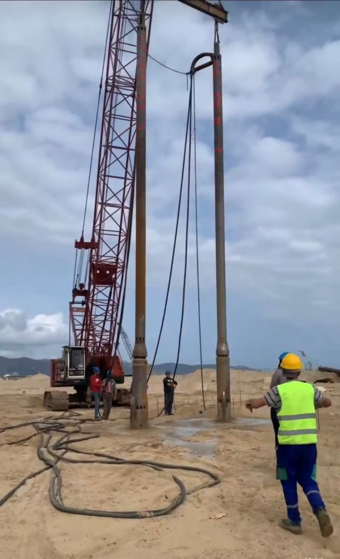
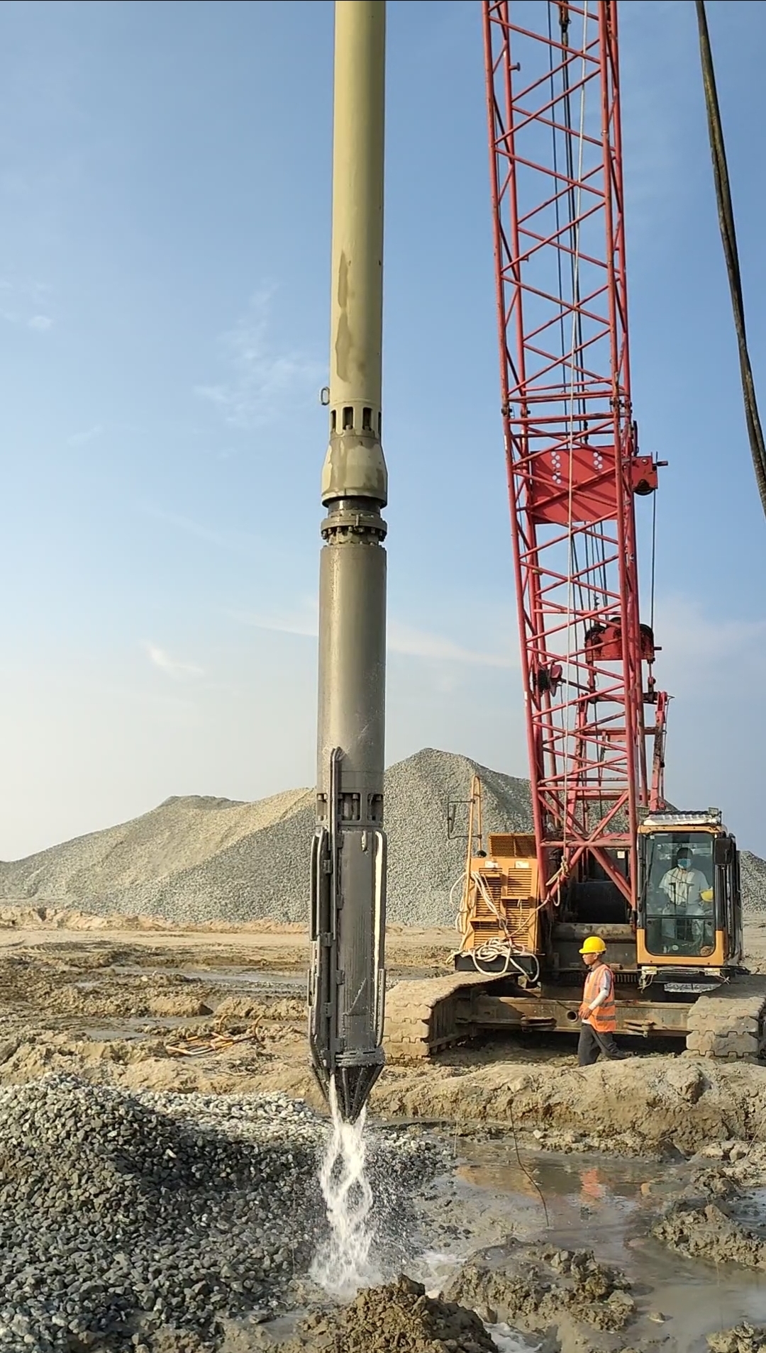
Penetration Phase: The heavy vibroflot is suspended from a crawler crane and positioned over the target location. The vibrator is energized, and high-pressure water jets located at the nose cone are activated. The combined action of horizontal vibratory force and hydraulic jetting fluidizes the loose sand, allowing the probe to penetrate under its own weight to the design depth ( 20.6 m).
Flushing & Cavity Preparation: Upon reaching the target depth into the stiff Q3 layer, water jetting pressure is reduced. The probe is moved up and down repeatedly to flush out fine silts and thoroughly clean the hole wall, establishing a stable annular cavity.
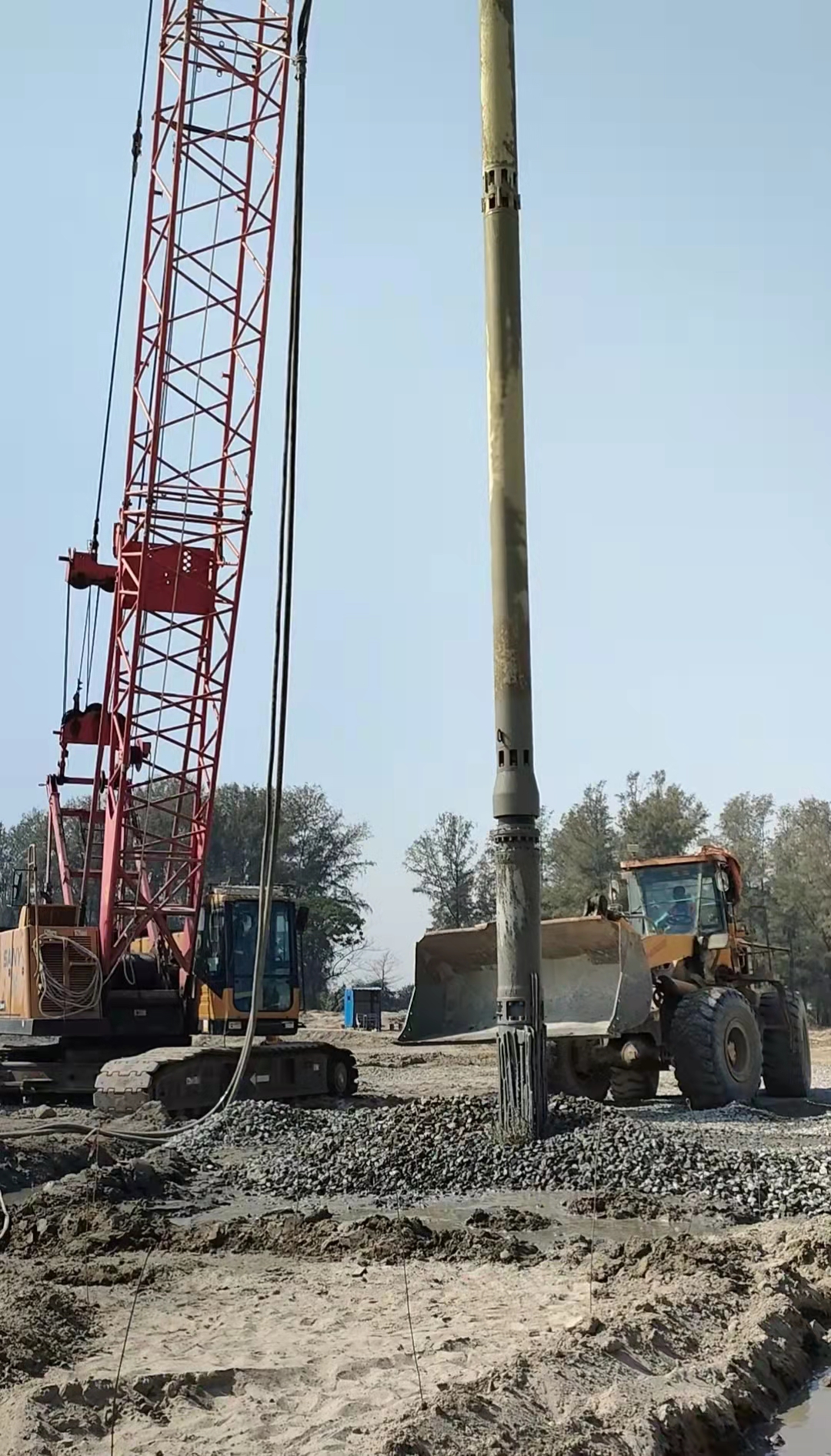
Backfilling & Compaction Cycle: Crushed aggregate is tipped at the ground surface using front loaders and washed down the annular space surrounding the probe by top-water flow. The probe is raised 0.5 m to 1.0 m to allow gravel to fill the cavity base, then lowered into the backfill. The vibratory action forces the gravel outward into the surrounding soil, compacting both the aggregate column and adjacent sand.
Step-by-Step Construction: This backfeeding and compaction process is repeated in controlled lifts up to the working ground surface, forming a continuous, dense, interlocking stone column.
Specialized Equipment Configuration
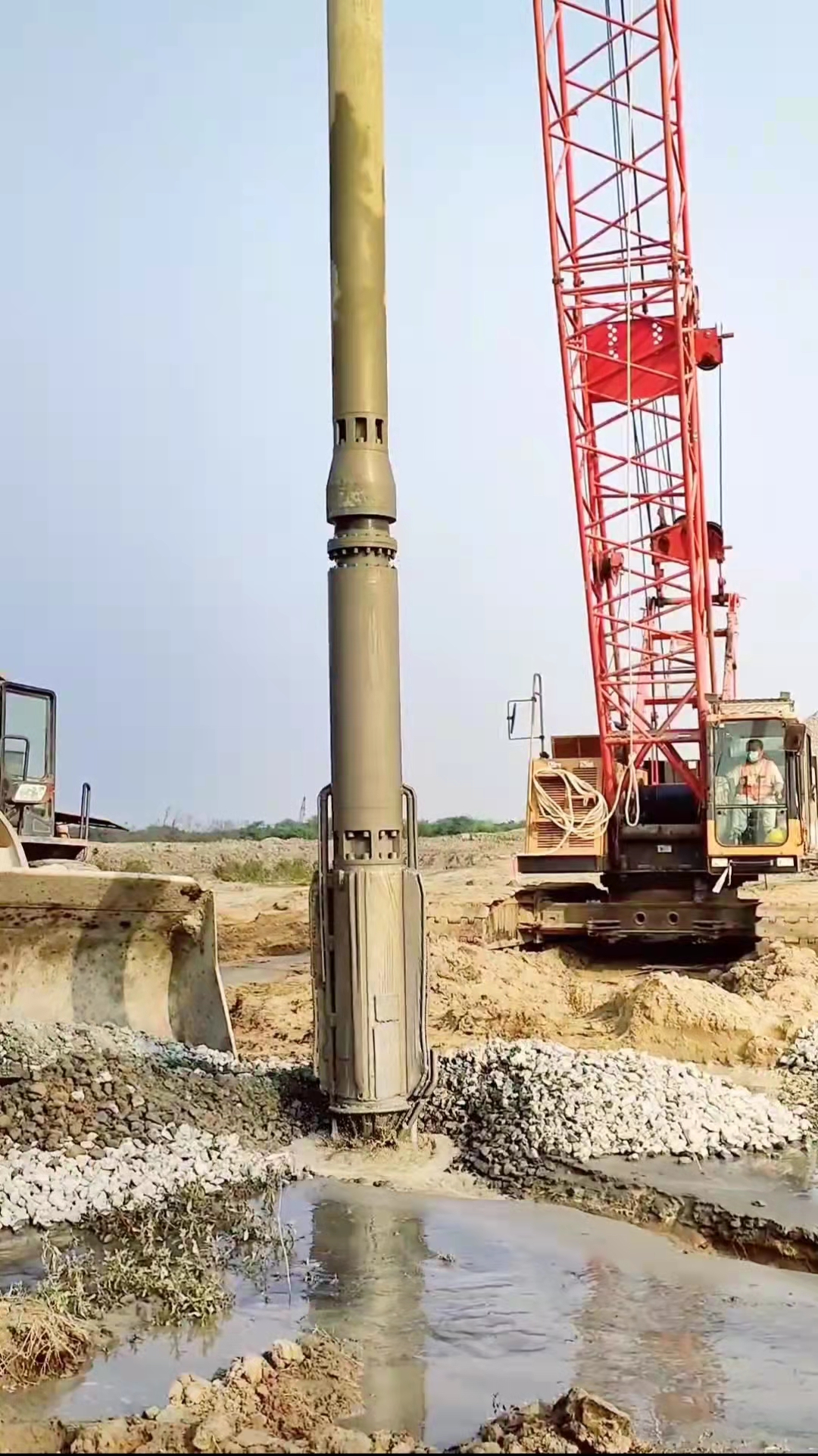
Execution required high-capacity equipment capable of maintaining continuous vibratory output under high lateral resistance:
Electric Vibroflots: High-torque vibratory probes rated at 100 kW and 130 kW, generating horizontal centrifugal forces between 200 kN and 350 kN at 1,500 rpm.
Auxiliary Plant:
Heavy-duty crawler cranes (50–70 ton capacity) with extended lattice booms for stable probe positioning.
High-pressure water pumps delivering 200–300 m³/h at pressures of 0.8–1.2MPa.
Heavy wheel loaders for continuous aggregate supply at the borehole mouth.
Real-time automated data logging systems inside the crane cab monitoring penetration depth, electrical current draw (Amperage), water pressure, and gravel volume consumption per lift.
Quality Assurance, Testing, and Engineering Outcome
Quality Control Parameters
Quality assurance was enforced through continuous digital monitoring during execution:
Amperage Control: Spikes in electric current (typically exceeding 180–220 Amperes for the 130 kW unit) served as a direct indicator of maximum aggregate compaction during each 0.5 m lift.
Aggregate Volume Consumption: Tracked per column meter to ensure the target replacement ratio (Ar≈ 20–25%) was consistently met.
Post-Treatment Verification Testing
To verify the mitigation of liquefaction risks, extensive post-construction testing was conducted after a minimum 14-day curing/stabilization period:
Standard Penetration Testing (SPT): N60 values in the inter-column sandy soil increased significantly from initial values of N = 4-8 to post-treatment values exceeding N≥18–25, far surpassing the minimum safety threshold against liquefaction for local seismic design codes.
Cone Penetration Testing (CPT): Tip resistance logs confirmed continuous, uniform compaction across the Q4 depth profile with no soft lenses remaining.
Plate Load Testing (PLT): Single-column and composite ground load tests confirmed an overall increase in composite subgrade modulus (Ks) and verified that the target allowable bearing capacity was achieved with negligible elastic deformation.
Conclusion
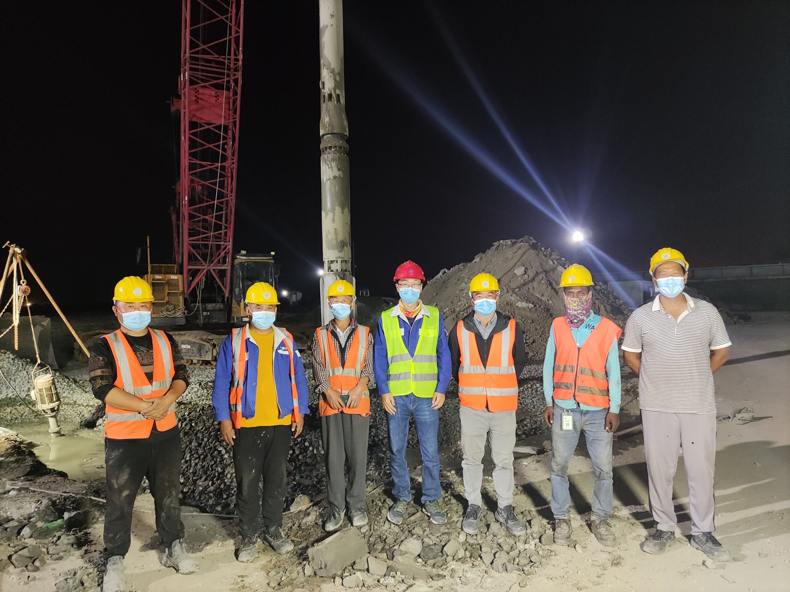
The implementation of the Vibro Replacement (Stone Column) technique across Section S2 of the Karnaphuli River Underwater Tunnel successfully addressed severe estuarine geotechnical risks. By transforming loose, liquefiable Holocene alluvial sand deposits into a high-strength, free-draining composite foundation, the project team effectively eliminated seismic liquefaction threats and controlled post-construction settlement. The operational success of high-power 100 kW/130 kW wet-process vibroflotation equipment in Chattogram offers a valuable engineering benchmark for similar coastal and estuarine underwater infrastructure projects globally.